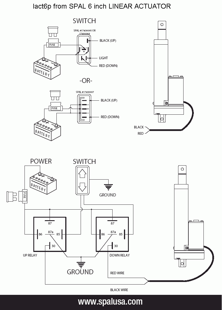
Linear Actuator Wiring Diagram
Make sure power is off before attempting to wire actuator. As shown in the diagram, bridging w2,u2, and v2.
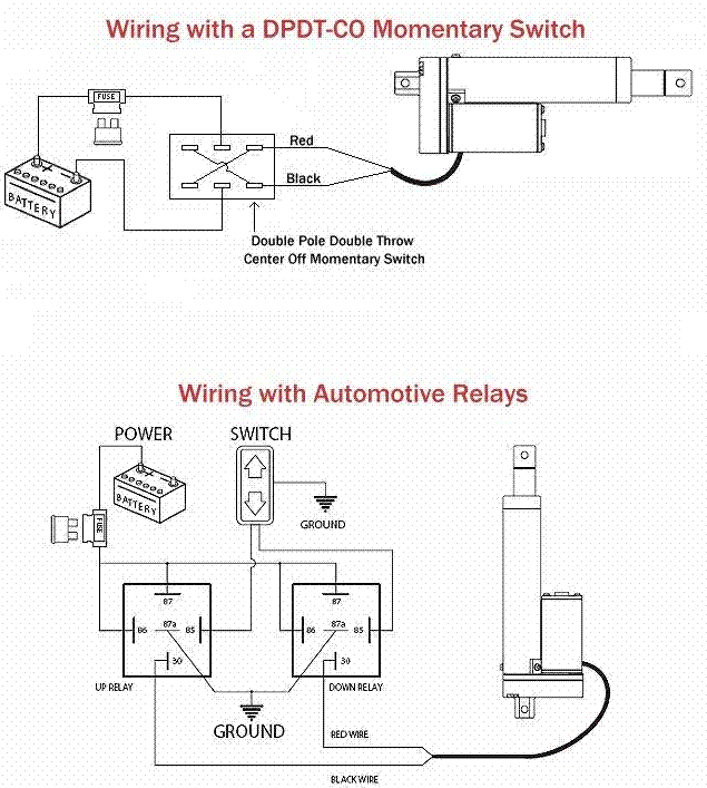
Below is a diagram showing you exactly how to wire up your actuator to a dpdt rocker switch.
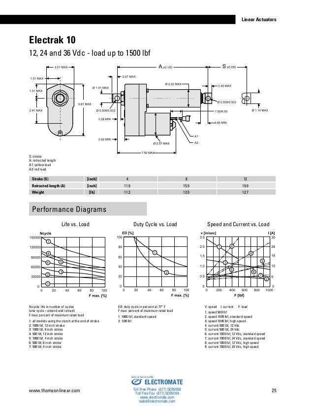
Linear actuator wiring diagram. If you selected 2 or more actuators for step one then you are presented If you selected 2 or more actuators for step one then you are presented with a few extra questions. The actuator and feedback potentiometer are connected to terminal block j1 as shown in the wiring diagram.
Select how many actuators you will be using. (if you selected 2 or more actuators, you will be presented with a few extra questions) pick which control options you wish to use. Wiring diagram of a rocker switch to an actuator the linear actuator wiring diagram above can be achieved by following a few steps:
The two diodes to the relay coils could be 1n4148s the diodes in parallel with the limit switches need to carry tha actuator current so i would suggest 3 amp rating diodes. This handy tool is used to give you the right linear actuator wiring diagram depending on your project requirements. Over 65 years of field service all over the world in oil and gas water and wastewater marine power generation refineries marine and chemical plants emerson s bettis and eim electric actuators have become the.
Generate a custom wiring diagram for your linear actuator projects. A beginner's guide to circuit diagrams. A first look at the circuit diagram might be confusing, but if search for a subway map, look for schematics.
Depends on the application, many users would prefer to control the linear actuator with a control box. The terminals have different designations. Select how many actuators you will be using.
This handy tool is used to give you the right linear actuator wiring diagram depending on your project requirements. Ships from and sold by amazon.com. A wiring diagram is an easy visual representation in the physical connections and physical layout of the electrical system or circuit.
Terminal 1 should be connected to the motor winding that moves the actuator toward the open position, and conversely, terminal 3 is connected to the winding that moves the actuator toward the closed position. Mpc linear actuators for wiring, switch and relay kit: This generator has been developed to show you how to connect your linear actuator (s) to our control system products to meet the specific needs of your project.
By reversing the actuator's two leads, it's possible to reverse this effect. Wiring diagram linear actuator actuator linear. They mostly plug and play, so there is very little need for additional wiring.
This is the suggested schematic. This diagram shows a simple wiring diagram that will allow you to manually switch power in either direction of the actuator travel. Along with our linear actuator calculator, our online tools will make designing your next project a breeze.
They can generally be summarized into two simple steps. Perfect instructions, worked perfectly for my. Wire gauge selection dc actuators long lead wires between the power source and the actuator will result in.
Firgelli automation is proud to present our linear actuator wiring diagram generator. Mpc 0462 linear actuators for wiring, switch and relay kit. It shows the way the electrical wires are interconnected and can also show where fixtures and components may be attached to the system.
Add on any additional features, such as a speed controller or external micro limit. Padgett's inmate number (your thoughts?) List of newspapers in manchester.
At progressive automations, we offer a large variety of control box options. This handy tool is used to give you the right linear actuator wiring diagram depending on your project requirements. Wiring thomson linear actuators should be connected in accordance with the diagram show below.
Refer to the following table for wire. How to use cutlery in a formal dinner Posted by feb 17, 2022 scotch strapping tape how to make a virtual prototype.
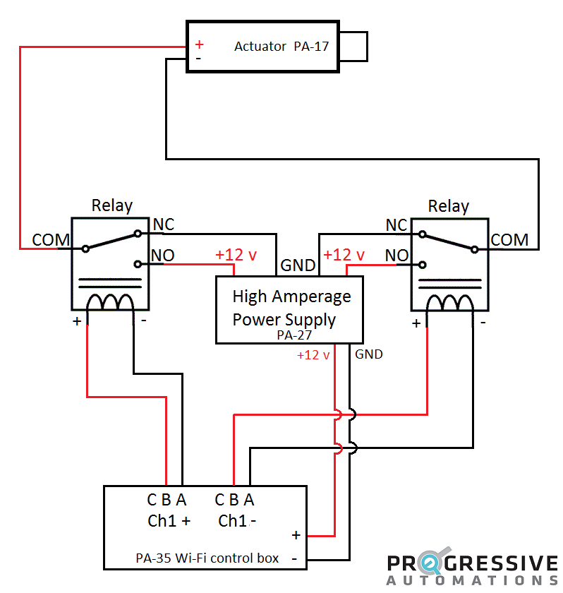
How to connect the actuonix relay kit i've included a wiring diagram below that shows you exactly how to connect your actuator to the actuonix relay kit. Wiring with a control box. Deadliest tornado near rome, metropolitan city of rome.
Linear actuator wiring diagram generator. Select how many actuators you will be using. You would need to solder a wire to the junction of the relay coil and it's driver transistor for each relay.

Linear Actuator Wiring Diagram Free Wiring Diagram

External Limit Switch Kit for Linear Actuators
12v Linear Actuator Wiring Diagram

Electric Linear Actuator Wiring Diagram Wiring Forums
Lub12 Wiring Diagram Download Wiring Diagram Sample

Linear Actuator Wiring Diagram Free Wiring Diagram

Rocker Switches for Linear Actuators Momentary and Sustaining Firgelli Automations

12 Volt Electric Linear Actuator Wiring Diagrams Progressive Automations
Linear Actuator, 12 Volt Motor

External LimitSwitch Kit for Actuators FIRGELLI

Linak Actuator Wiring Diagram Sample

Feedback Rod Linear Actuator Firgelli Automations

Linear Actuator Wiring Diagram Free Wiring Diagram

12v Linear Actuator Wiring Diagram

How to Wire Up a Linear Actuator to a Rocker Switch 12V Actuators

12v Linear Actuator Wiring Diagram Wiring Diagram Schemas
Wiring Diagram for Linear Actuator The Friendliest Tractor Forum and Best
